You are using an out of date browser. It may not display this or other websites correctly.
You should upgrade or use an alternative browser.
You should upgrade or use an alternative browser.
Circuit Diagram
- Thread starter Student_0
- Start date
Hi,
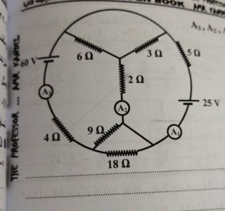
One way to calculate the theoretical readings of ideal ammeters placed at those locations is to apply Kirchhoff's laws to the nodes and loops of the given circuit.
In analyzing the circuit using Kirchhoff's Current Law, we would write down the sum of all incoming and outgoing branch currents at each node of the circuit.
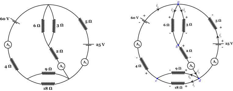
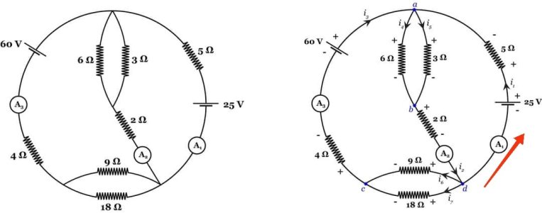
Note that the given illustration of the circuit has 2 extraneous branches: the 2 branches that have no circuit elements have no effect on the branch currents or branch voltages in the rest of the circuit, assuming those branches represent ideal conductors. As such, it may be best to redraw the diagram, reducing those extraneous branches to nodes (see the left diagram in the attached image).
The redrawn circuit diagram has only 4 nodes, labeled a, b, c, and d in the attached diagram (the blue dots in the right diagram).
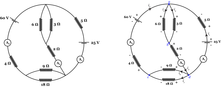
We may then set up the directions of branch currents into and out of each node by following the associated variables convention, or passive sign convention (if the actual current direction is opposite to this, we will just get a negative branch current value in the solution).
There are 7 branches in total, so we have 7 branch currents to find. We will let current flowing into a node be added to the sum, while current flowing out is subtracted (the reverse can also be done; the results will be the same). For the node labeled "a", for example, we get the equation:
i₁ + i₃ - i₄ - i₅ = 0
Similarly, for nodes b and c, we get:
i₄ + i₅ - i₂ = 0
i₆ + i₇ - i₃ = 0
There is no point in writing down the current law for node d because it will be linearly dependent on the equations we have already written, and as such carries no new information.
So far we have 3 linearly independent linear equations in 7 unknowns, so from linear algebra, we know that we need at least 4 more linearly independent equations in order to find a unique solution.
We can get those equations from applying Kirchhoff's Voltage Law to the 4 internal loops of our circuit diagram. Recall Kirchhoff's Voltage Law states that the sum of the branch voltages in a circuit loop must be 0.
Going clockwise around each loop, we get the equations:
60 - 4i₃ - 9i₆ - 2i₂ - 6i₄ = 0
9i₆ - 18i₇ = 0
5i₁ + 3i₅ + 2i₂ - 25 = 0
6i₄ - 3i₅ = 0
Now that we have an inhomogeneous system of 7 linearly independent linear equations in 7 unknowns, we know from linear algebra that there is either 1 unique solution or no solution.
In this case, there is 1 unique solution, which gives us the branch currents for the associated ammeters: i₁ = 1 A, i₂ = 5 A, and i₃ = 4 A.
Note that you can also reduce your work by treating the pair of 3Ω and 6Ω resistors as a single 2Ω effective resistor, and similarly treating the pair of 9Ω and 18Ω resistors as a single 6Ω effective resistor, since there are no ammeters on those separate branches.
Note that if you have already derived the circuit laws for combining resistors in series and in parallel from Kirchhoff's circuit laws, then you can simplify the diagram considerably, first by combining the two pairs of parallel resistors into effective resistors, then by combining these effective resistors with the resistors they are in series connection with (see the attached diagram), yielding an effective circuit diagram that differs considerably from the original diagram, but has the same branch currents through the three given ammeter locations.
View attachment CircuitDiagram2-01.png
This new diagram has only two nodes, and thus only one linearly independent Kirchhoff's current law:
i₁ + i₃ - i₂ = 0
The remaining two linearly independent equations that we need can come from applying Kirchhoff's voltage law to the two internal loops:
4i₂ + 10i₃ - 60 = 0
25 - 5i₁ - 4i₂ = 0
This inhomogeneous system of 3 linearly independent equations in 3 unknowns has the same unique solution as before.
One way to calculate the theoretical readings of ideal ammeters placed at those locations is to apply Kirchhoff's laws to the nodes and loops of the given circuit.
In analyzing the circuit using Kirchhoff's Current Law, we would write down the sum of all incoming and outgoing branch currents at each node of the circuit.
Note that the given illustration of the circuit has 2 extraneous branches: the 2 branches that have no circuit elements have no effect on the branch currents or branch voltages in the rest of the circuit, assuming those branches represent ideal conductors. As such, it may be best to redraw the diagram, reducing those extraneous branches to nodes (see the left diagram in the attached image).
The redrawn circuit diagram has only 4 nodes, labeled a, b, c, and d in the attached diagram (the blue dots in the right diagram).

We may then set up the directions of branch currents into and out of each node by following the associated variables convention, or passive sign convention (if the actual current direction is opposite to this, we will just get a negative branch current value in the solution).
There are 7 branches in total, so we have 7 branch currents to find. We will let current flowing into a node be added to the sum, while current flowing out is subtracted (the reverse can also be done; the results will be the same). For the node labeled "a", for example, we get the equation:
i₁ + i₃ - i₄ - i₅ = 0
Similarly, for nodes b and c, we get:
i₄ + i₅ - i₂ = 0
i₆ + i₇ - i₃ = 0
There is no point in writing down the current law for node d because it will be linearly dependent on the equations we have already written, and as such carries no new information.
So far we have 3 linearly independent linear equations in 7 unknowns, so from linear algebra, we know that we need at least 4 more linearly independent equations in order to find a unique solution.
We can get those equations from applying Kirchhoff's Voltage Law to the 4 internal loops of our circuit diagram. Recall Kirchhoff's Voltage Law states that the sum of the branch voltages in a circuit loop must be 0.
Going clockwise around each loop, we get the equations:
60 - 4i₃ - 9i₆ - 2i₂ - 6i₄ = 0
9i₆ - 18i₇ = 0
5i₁ + 3i₅ + 2i₂ - 25 = 0
6i₄ - 3i₅ = 0
Now that we have an inhomogeneous system of 7 linearly independent linear equations in 7 unknowns, we know from linear algebra that there is either 1 unique solution or no solution.
In this case, there is 1 unique solution, which gives us the branch currents for the associated ammeters: i₁ = 1 A, i₂ = 5 A, and i₃ = 4 A.
Note that you can also reduce your work by treating the pair of 3Ω and 6Ω resistors as a single 2Ω effective resistor, and similarly treating the pair of 9Ω and 18Ω resistors as a single 6Ω effective resistor, since there are no ammeters on those separate branches.
Note that if you have already derived the circuit laws for combining resistors in series and in parallel from Kirchhoff's circuit laws, then you can simplify the diagram considerably, first by combining the two pairs of parallel resistors into effective resistors, then by combining these effective resistors with the resistors they are in series connection with (see the attached diagram), yielding an effective circuit diagram that differs considerably from the original diagram, but has the same branch currents through the three given ammeter locations.
View attachment CircuitDiagram2-01.png
This new diagram has only two nodes, and thus only one linearly independent Kirchhoff's current law:
i₁ + i₃ - i₂ = 0
The remaining two linearly independent equations that we need can come from applying Kirchhoff's voltage law to the two internal loops:
4i₂ + 10i₃ - 60 = 0
25 - 5i₁ - 4i₂ = 0
This inhomogeneous system of 3 linearly independent equations in 3 unknowns has the same unique solution as before.
Thank you for this wonderful explanation. I have several questions:
Q1: What battery does current flow from?
Q2: Is the “25V” battery a charging battery while the “60V” battery is a discharge battery?
Q3: How did you know that the two 3.6 ohm resistors were connected in parallel?
Can you show me using the arrows the loops you took in this figure?
Why was this part of the circuit deleted?
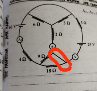
Why didn't current I2 follow this path?
Q1: What battery does current flow from?
Q2: Is the “25V” battery a charging battery while the “60V” battery is a discharge battery?
Q3: How did you know that the two 3.6 ohm resistors were connected in parallel?
Can you show me using the arrows the loops you took in this figure?

Why was this part of the circuit deleted?

Why didn't current I2 follow this path?

Q1: What battery does current flow from?
In the solution, all branch currents have positive values, which means the directions of the branch currents match the directions of the actual currents in the circuit. The directions of the branch currents were chosen (as shown in the diagram) to align with the conventional current direction associated with each voltage source (outwards from the positive terminal). As such, current is flowing from both batteries.
Q2: Is the “25V” battery a charging battery while the “60V” battery is a discharge battery?
In this circuit, both batteries are discharge batteries (just as if they were connected in parallel), since current flows through both batteries in the correct direction for each battery's voltage orientation.
Q3: How did you know that the two 3.6 ohm resistors were connected in parallel?
Assuming you mean the 3-ohm resistor and the 6-ohm resistor, two resistors are said to be connected in parallel if they are on different branches, but share the same pair of terminal nodes in a circuit diagram in which distributed nodes have been simplified (in our simplified diagram, the pair of terminal nodes are the nodes labeled "a" and "b").
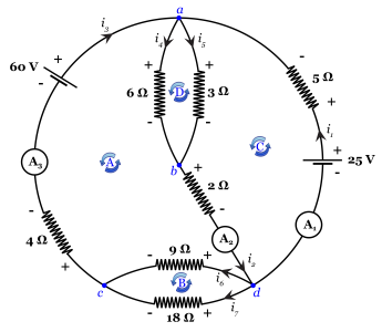
The 4 loops used for Kirchhoff's Voltage Law are shown as A, B, C, and D in the attached diagram (all are taken counterclockwise). They are labeled alphabetically in the same order as they are written in the original reply:
From the voltage point of view, in the two loops containing this branch (loops B and C in the previous comment) , the branch appears as nothing more than an extension of the terminals of the two circuit elements on either side (the two resistors in loop B, and the two ammeters in loop C). As such, it also plays no part in Kirchhoff's Voltage Law.
Re: current i₂: Each branch has its own branch current. Unless you have applied Kirchhoff's Current Law or a more fundamental law, and found otherwise, there is no reason to believe the current on either side of a node will be the same, unless the node only has two branches (that last part is implied by Conservation of Charge).
The node that branch current i₂ flows into has 4 branches (with branch currents i₁, i₂, i₆, and i₇), so we cannot make a coherent conclusion until we analyze the interaction of the branch currents in all of those branches with each other via conservation of charge (which ultimately results in Kirchhoff's Current Law).
In the conventional hydrodynamic analogy, branch current i₂ being diverted solely into branch current i₁ at the junction of 4 branches would be like a pipe that splits into three outlet pipes, where the water that enters the junction "magically" goes down only one of the three pipes instead of being distributed through the 3 outlet pipes (dependent on the water pressure and cross-sectional area of each pipe).
In the solution, all branch currents have positive values, which means the directions of the branch currents match the directions of the actual currents in the circuit. The directions of the branch currents were chosen (as shown in the diagram) to align with the conventional current direction associated with each voltage source (outwards from the positive terminal). As such, current is flowing from both batteries.
Q2: Is the “25V” battery a charging battery while the “60V” battery is a discharge battery?
In this circuit, both batteries are discharge batteries (just as if they were connected in parallel), since current flows through both batteries in the correct direction for each battery's voltage orientation.
Q3: How did you know that the two 3.6 ohm resistors were connected in parallel?
Assuming you mean the 3-ohm resistor and the 6-ohm resistor, two resistors are said to be connected in parallel if they are on different branches, but share the same pair of terminal nodes in a circuit diagram in which distributed nodes have been simplified (in our simplified diagram, the pair of terminal nodes are the nodes labeled "a" and "b").
The 4 loops used for Kirchhoff's Voltage Law are shown as A, B, C, and D in the attached diagram (all are taken counterclockwise). They are labeled alphabetically in the same order as they are written in the original reply:

This branch was reduced to a node, since it has no circuit elements, and is thus no different from a circuit where its two endpoints coincide (any current flowing into one endpoint will flow out the other end unimpeded, since there are no circuit elements to interact with). As such, it plays no part in Kirchhoff's Current Law.Why was this part of the circuit deleted?
View attachment 8
From the voltage point of view, in the two loops containing this branch (loops B and C in the previous comment) , the branch appears as nothing more than an extension of the terminals of the two circuit elements on either side (the two resistors in loop B, and the two ammeters in loop C). As such, it also plays no part in Kirchhoff's Voltage Law.
Re: current i₂: Each branch has its own branch current. Unless you have applied Kirchhoff's Current Law or a more fundamental law, and found otherwise, there is no reason to believe the current on either side of a node will be the same, unless the node only has two branches (that last part is implied by Conservation of Charge).
The node that branch current i₂ flows into has 4 branches (with branch currents i₁, i₂, i₆, and i₇), so we cannot make a coherent conclusion until we analyze the interaction of the branch currents in all of those branches with each other via conservation of charge (which ultimately results in Kirchhoff's Current Law).
In the conventional hydrodynamic analogy, branch current i₂ being diverted solely into branch current i₁ at the junction of 4 branches would be like a pipe that splits into three outlet pipes, where the water that enters the junction "magically" goes down only one of the three pipes instead of being distributed through the 3 outlet pipes (dependent on the water pressure and cross-sectional area of each pipe).
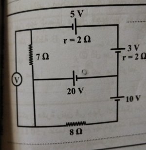
I would first simplify the circuit by reducing any distributed nodes to single nodes, as we did in the previous circuit, then by writing the batteries with internal resistance as equivalent branches: a battery with 0 internal resistance connected in series with a resistor of the requisite resistance. Place the resistor on the most convenient side of the battery for further circuit simplification, such as combining any resistors that are in series or parallel into single equivalent resistors.
Once you do this, you will see that the voltmeter is connected solely across the 7 Ω resistor in the picture, and we know from Ohm's Law that it must therefore read V = IR, where I is the current through the resistor and R is 7 Ohms. You must then solve the circuit for the current through that branch in order to compute V.
Once you do this, you will see that the voltmeter is connected solely across the 7 Ω resistor in the picture, and we know from Ohm's Law that it must therefore read V = IR, where I is the current through the resistor and R is 7 Ohms. You must then solve the circuit for the current through that branch in order to compute V.
